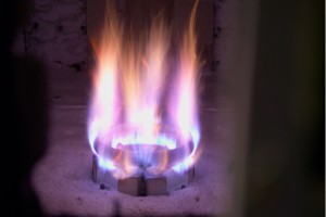
“Photo of a new ultra-low NOx process burner firing a refinery fuel gas mixture in a relatively cold test furnace at a low firing rate. The burner incorporates some advanced aerodynamic mixing techniques and is called the HALO burner because of the ceramic ring at the outlet.”
Chuck Baukal (John Zink Company)

“A candle structure includes a candle body and a plurality of wicks. The candle body is configured with a top and bottom surface, and an outside wall that tapers substantially inward from the top surface to the bottom surface. The plurality of wicks is configured to supply stable preheated air through the gaps of standing wicks that protrude from the top surface of the candle structure. The plurality of wicks extends above the body and the wicks are aligned longitudinally. The plurality of wicks is arranged radially to taper outward toward the bottom surface of the candle body such that a flame is produced when the wicks are ignited. An air channel is configured to supply stable preheated air to a base of the flame, the air channel extending through the plurality of wicks and being graduated so that the flow of air through the air channel is substantially laminar. A heat conductive rod extending downward from a top of the air channel, wherein the heat conductive rod is configured to increase the temperature of and lower the air pressure of the air at the top of the air channel. It further maintains stable preheated air supply to the base of the flame. As a result, the flame is larger with less smoke and unburned fuel, stronger and less susceptible to air disturbances such as wind. When the wind gets strong, the adequately warmed air, passing through the air channel, increases. It increases the strength of the flame. The stronger the wind blows, the tougher the flame stands without smoke.”
Susumu Matsuyama (Almond Lamp Company)
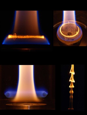
“The images shown are photographs of ethylene/air/nitrogen diffusion flames stabilized behind a bluff centerbody. The two images on the top show the centerbody flame photographed from the side (top left) and top views (top right). The blue regions are associated with the flame front and the other colors of the flame are largely due to blackbody radiation from the soot. The intense yellow radiation is from soot trapped in a tight ring vortex downstream of the stabilizing bluff body. The motion of the soot trapped in the vortex can be seen in the longer exposure photograph taken from the top.
The bottom two images are of a centerbody flame with the same inlet flow velocities as the case shown above but with higher nitrogen content in the feed gases. The image on the lower left shows a blue ring flame that forms around the main flame immediately downstream of the centerbody. This blue ring flame exhibits a slight oscillation in the vertical direction. The image on the lower right shows the region downstream of the ring flame for the same conditions. The disturbances in the downstream region of the flame are amplified as it passes through the tube, resulting in the large structures shown in the short exposure (0.8 ms) photo.”
Scott Stouffer, Garth Justinger (University of Dayton Research Institute), Mel Roquemore, Amy Lynch, Vince Belovich, Joe Zelina, Jim Gord (Air Force Research Laboratory, Wright Patterson Air Force Base), Keith Grinstead, Vish Katta and Kyle Frische (Innovative Scientific Solutions Incorporated)