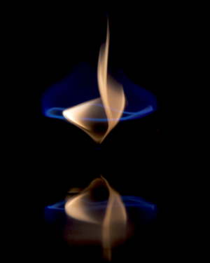
“The ‘blue whirl’ is a newly discovered flame structure that naturally evolves from a traditional yellow fire whirl under specific conditions of fuel flow and air circulation. While a traditional yellow fire whirl is known to be sooty, the blue whirl (typically ~8 cm high) is seen to be completely blue, indicating the absence of soot in the flame. This image shows an instance of a yellow fire whirl transitioning to a blue whirl. Such transitions show yellow streaks of soot that travel downwards into the flame, and swirl within the blue conical structure.
This image was captured using a Nikon D7100 at f/5.3 with an exposure time of 3.125 ms. A visible blue ring forms the edge of the blue conical structure, with the yellow soot trace within it. Since the flame is formed using n-heptane poured over a water surface, a mirror reflection of the flame is seen below.”
Sriram Bharath Hariharan, Michael J. Gollner, and Elaine S. Oran (University of Maryland)
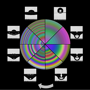
“In IC engines, deposition of fuel droplets on the engine walls is highly undesirable as it facilitates fuel-rich burning, incomplete combustion and soot formation. When a droplet impacts a liquid surface, it traps a microscopic air-film underneath, which provides a cushioning effect. If the cushioning is strong enough, the droplet can actually bounce from the surface instead of merging with it. The air-film cannot be seen directly, and its miniscule thickness (~1 micron) also cannot be easily measured. In this experiment we shone a white light from the bottom of a wetted glass surface, and observed beautiful interference patterns, just like the rainbow colors on a soap bubble. Different colors represent different thicknesses of the air-film from which the shape of the air-film can be spatially resolved.
Here, we portray the life-cycle of this air cushion upoon droplet impact, with each slice representing a time instant. The impact starts from the 12 o’clock position and time lapses clockwise. The first two slices are when the droplet is approaching the surface and the rest are when the droplet is leaving the surface. Surrounding side-view images show relative droplet locations.”
Xiaoyu Tang, Abhishek Saha, and Chung K. Law (Princeton University)
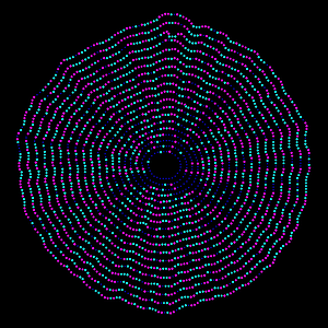
“Otherwise regular and smooth surface of an expanding flame can be converted into irregular and wrinkled morphology either by cellular instability or by turbulence. Under both these situations, wrinkling of flame-front becomes stronger as the flame grows, either by the increase in number of cells or by the effect of larger eddies. While these wrinkled flame-fronts consist of segments with widely varying local curvatures, it is interesting to watch how locally the curvature evolves with time.
If the instantaneous flame edges from various time instances colored by the local curvature are superimposed for expanding wrinkled flames, beautiful patterns emerge. Two of such flames are portrayed here, Top row: Cellularly unstable laminar flame and Bottom row: Turbulent expanding flame, with colors representing negatively (green circle), positively (pink circles) and weakly (blue dots) curved flame segments. Amidst the beautiful plethora of colorful dots, the evolution of local curvature can be visualized by tracing the same color dots.”
Abhishek Saha, Sheng Yang, and Chung K. Law (Princeton University)
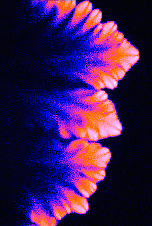
“A Hele-Shaw cell is used for this laminar flame instability research. Dimensions of entire visible area is 15.75in by 23.62in. The Hele-Shaw cell is first evacuated, and then filled with desired premixed gas mixture using partial pressure method. The gas mixture is ignited at one end of the cell by three ignition sparks. The flame propagates under constant pressure toward the closed end of the cell with ignition end open to the atmosphere. There is no turbulence pre-ignition in the cell. Light emitted from hot products behind flames is filmed in total darkness. The video contains several individual experiments of different gas mixtures and propagation orientations. They are also colored using Adobe Premiere during post process. The conditions for each experiments are:
- C3H8-O2-N2 mixture with equivalence ratio of 2 and calculated adiabatic flame temperature around 1850K horizontally propagation through a 0.5in narrow gap between two plates.
- H2-O2-N2 flames of equivalence ratio of 2 and calculated adiabatic flame temperature around 1200K downward propagating through a 0.5in narrow gap between two plates.
- H2-O2-N2 flames of equivalence ratio of 2 and calculated adiabatic flame temperature around 1200K horizontally propagating through a 0.5in narrow gap between two plates.
- H2-O2-CO2 flames of equivalence ratio of 0.2 and calculated adiabatic flame temperature around 900K upward propagating through a 0.5in narrow gap between two plates.
- H2-O2-CO2 flames of equivalence ratio of 0.8 and calculated adiabatic flame temperature around 1200K downward propagating through a 0.25in narrow gap between two plates.
- H2-O2-N2 flames of equivalence ratio of 0.8 and calculated adiabatic flame temperature around 1300K horizontally propagating through a 0.5in narrow gap between two plates.
- H2-O2-CO2 flames of equivalence ratio of 0.35 and calculated adiabatic flame temperature around 1050K downward propagating through a 0.5in narrow gap between two plates.
Otherwise regular and smooth surface of an expanding flame can be converted into irregular and wrinkled morphology either by cellular instability or by turbulence. Under both these situations, wrinkling of flame-front becomes stronger as the flame grows, either by the increase in number of cells or by the effect of larger eddies. While these wrinkled flame-fronts consist of segments with widely varying local curvatures, it is interesting to watch how locally the curvature evolves with time.
If the instantaneous flame edges from various time instances colored by the local curvature are superimposed for expanding wrinkled flames, beautiful patterns emerge. Two of such flames are portrayed here, Top row: Cellularly unstable laminar flame and Bottom row: Turbulent expanding flame, with colors representing negatively (green circle), positively (pink circles) and weakly (blue dots) curved flame segments. Amidst the beautiful plethora of colorful dots, the evolution of local curvature can be visualized by tracing the same color dots.”
Si Shen (University of Southern California)
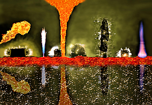
“The image is a combination of non-premixed, premixed, and solid propellant combustion.”
Sayan Biswas, Aman Satija, Michael Powell, Morgan Ruesch, Steven Son, Robert Lucht, and Li Qiao (Purdue University)
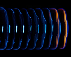
“The counterflow flame burner consists of two opposed vertically-oriented concentric burners. The upper burner supplies the fuel jet and the lower burner supplies the oxidizer jet. The two center jet exits are surrounded by a co-flow to shield the flame from the environment resulting in the circular flame shape. To capture the sequenced temporal evolution of the flame, we first ran the methane and air through the upper and lower parts of the counterflow burner respectively before the mixture was ignited. That results in a large rich flame around the upper part of the counterflow burner. After that, we introduced nitrogen as the co-flow gas to shield the flame. As we increased the rate of the co-flow, the inner circular flame started to shape. Finally, we decreased the oxidizer flow rate in order to shrink the flame. The pictures were taken through all the steps.”
Radi Alsulami and Colin Gould (Colorado State University)